Golf Putters
As the Engineering Design Intern at Motor Head Putters, I led the end-to-end design of new golf putters using SolidWorks, combining advanced 3D modeling to create optimized cast steel structures. I worked closely with co-founders of the startup to explore design directions, conduct market research, and ensure all prototypes met USGA regulations. Throughout the process, I produced over 20 physical prototypes using 3D printing to refine performance through iterative testing. Final designs featured improved weight distribution and stroke stability.
Iteration I
This putter is designed to handle the variety of hosel input designs that are regularly welded into position and then sequentially bent to the correct offset and lie angle. The versatility in this design promotes a way to vary the amount of toe flow based on where the hosel is located on the putter. The shaft axis' intersection with a putter’s center of gravity is how to vary the amount of Toe Flow created.

Iteration II
This putter is designed for use with a shafted center, promoting a lie angle balanced bias. The shaft axis is aligned with the putter’s center of gravity in all directions, which was achieved with the use of weights to set the material in the Z axis and implemented on the sole of the putter to bring the center of gravity to the face. A lie angle-balanced putter results in maximum stroke stability.

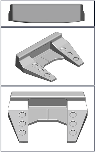
Iteration III
This D-shaped mallet putter is designed for use with a double-bend shaft, promoting a face-balanced stroke. The shaft axis is aligned with the putter’s center of gravity in both the X and Y axes, resulting in a balanced toe flow and improved stability throughout the putting stroke.

Final Product
I coordinated with a foundry to produce a metal casting from scrap cast iron and steel and created six of my designed putters to be used by golfers. These putters featured a flow neck hosel with 70 degrees of lie angle and added 3.5 degrees of loft by process of milling on a Bridgeport mill.